-
Respect the standards, regulations, and laws in force.
-
All work on the machine must be carried out by qualified personnel only.
-
Unless otherwise specified, the instructions in this section should be carried out with clean water only.
-
Wear the necessary PPE.
Identification plates
Presence and position of manufacturer's plates:
-
Spraying module plate
-
Dual tank module plate
-
Pump plate
Preliminary checks
-
Visually check that the machine is clean. If necessary, clean the machine according to the procedure of the Cleaning after treatment chapter.
-
Visually check the machine for any traces of herbicides, fungicides, insecticides, or fertilizers.
-
Check that the tire pressure is 2.0 bar | 29 psi.
-
Check that all components indicated on the spraying module and dual tank module are present and visually in good condition.
-
Check that the safety-related equipment is present as described in the Road safety devices and requirement chapter (Road safety devices and requirement).
-
Check the power take-off.
-
Perform a general operating check.
Hitching
-
The machine must be hitched in accordance with the Sprayer hitching and Tank system hitching chapters (Sprayer hitching & Tank system hitching)
-
Connect the PTO as shown in the Safety instructions chapter (Safety instructions).
Fluidic system leakage
There must be no leakage from the sprayer fluidic system. Visually check the fluidic system for leaks.
Refer to the Fluidic diagram if necessary (Fluidic diagram).
Frame and support parts
Visually check that all supporting parts and the frame are in good condition, with no anomalies, extreme corrosion or other defects that could affect the operation of the machine.
Locking of foldable / collapsible parts
According to Handling of the lateral modules:
-
Check that the safety hooks and actuating strings are present and functional before lifting or lowering the modules.
-
Check that the side modules can be operated.
Requirements for the machine
Leaks (with pump off)
-
Fill both tanks to the half of their capacity with water.
-
Keep the pump stopped.
-
Visually check that no fluid is leaking from any part of the machine.
-
Visually check the tanks for cracks, holes, or other openings through which some fluid may leak.
Leaks (with pump running and without spraying)
-
Fill both tanks with water to half their capacity.
-
Make sure that the pressure is 4.0 bar | 58 psi.
-
Visually check the machine for leaks.
Leaks (with pump running and spraying)
-
Fill both tanks to the half of their capacity with water.
-
Open the nozzles as described in chapter Nozzle check.
-
Visually check the machine for leaks.
Spraying on the sprayer
This test ensures that the machine is not spraying on itself.
-
Fill both tanks to the half of their capacity with water.
-
Visually check that no liquid is sprayed on any part of the sprayer or on any protections.
Pump
For measurements on the pump, the coupling dimensions are BSP 1 1/4″.
Spray pump flow rate
-
Open the discharge circuit at the pump level.
-
Connect a flow meter and a liquid collecting system.
-
Turn on the pump.
-
Take the flow measurement. The flow rate must be 60 l/min | 16 US gpm.
Spray pressure pulses
-
The pump pulse amplitudes are checked.
-
Sprayer control system start.
-
Check that the pressure is 3 bar | 44 psi on the tablet.
Agitators
Check that the agitation is visible.
![]()
Mixture tank
Lids
Visually check that the lids of both tanks are present and in good condition.
Filling hole
Visually check that the orifices of both tanks are present and not obstructed.
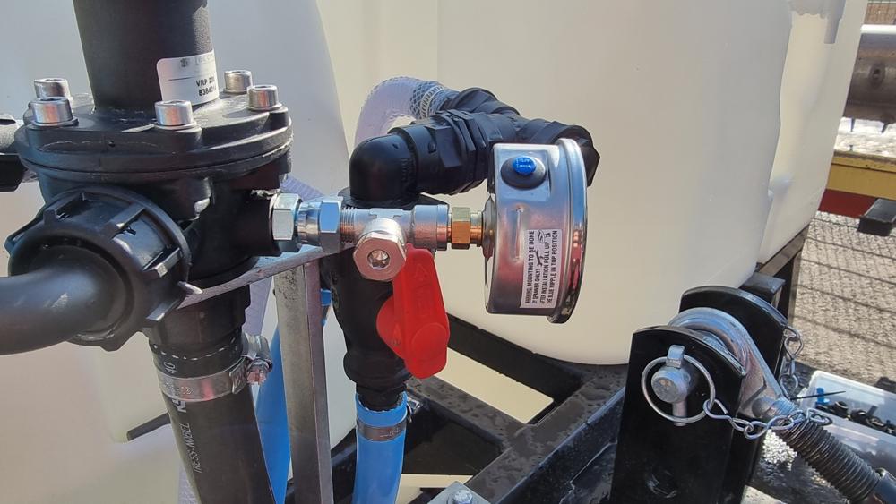
Pressure compensation
Visual control of the presence and functioning of the overpressure regulation on the phytosanitary tank as well as the pressure regulation valve on the machine.
Level indicator
Visually check that the liquid level indicator in the mixture tank or in the entire tank assembly is sufficiently visible and legible from the driver's seat and from the place where the machine is filled.
Draining the mixture tank
Test both tank drain valves. (Water drain (33) and Mixture drain (34) on the Fluidic diagram (Fluidic diagram).
Measuring, control and regulation systems
Condition and operation
-
All instruments and controls present on the machine, which are required for measuring, regulating, and controlling the field sprayer, function properly.
-
Check whether the machine can be switched on with the ON/OFF button on the HMI.
-
Check that the tablet is working.
-
Verify that the tablet can connect to the unit's Wi-Fi.
-
Check that the pump starts by engaging the tractor's front hydraulic unit.

-
Check that the pump stops and starts by positioning the general valve horizontally and then vertically.
Start the liquid circulation in the system.
-
Check that the pressure gauge on the dispensing system indicates pressure.
-
Check that the tablet indicates pressure.
-
On the tablet, open and close all nozzles.
Accessibility
-
From the tractor cab:
-
Check that the level indicator is legible over the entire height.
-
Check that the distribution system pressure gauge is readable.
-
Check that the tablet is functional.
-
-
On the dual tank module:
-
Check that the pressure regulator is working by slightly changing the pressure and reading the value returned by the pressure gauge.
-
Operation of the ramp sections
-
Put the fluidic circuit under pressure.
-
On the app, activate Flushing mode.
-
Successively test the spray booms one by one by activating and deactivating the different 2-meter sections in the user interface on the tablet.
-
Check that the booms are spraying.
Operation of the ramp sections
Checking the speed
-
On the user interface, create a mission and launch it.
-
Drive the machine at a constant speed over a straight distance.
-
Check that the speed indicated on the tablet corresponds to the speed indicated on the tractor's counter (deviations of about ± 0.5 km/h | 0.31 mph are normal).
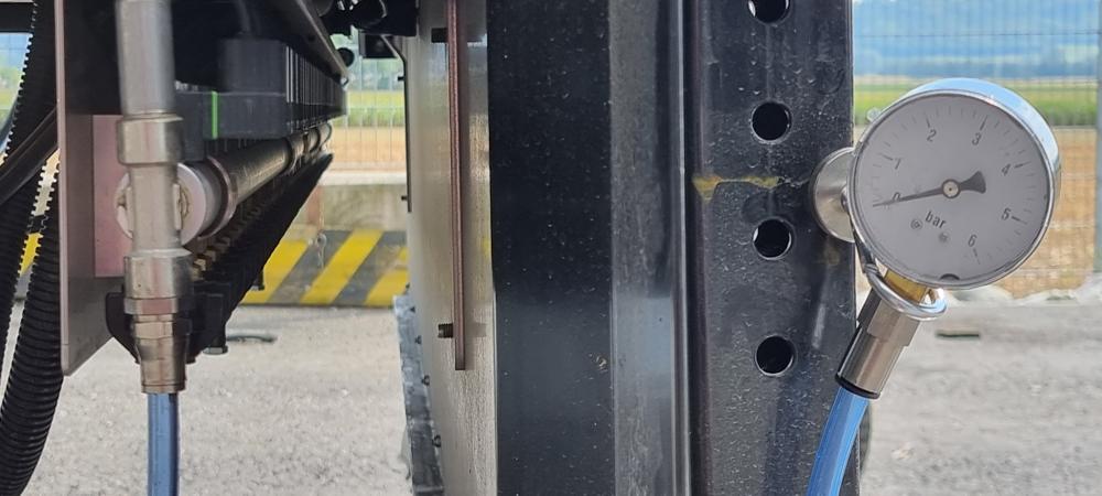
Checking the pressure gauge
-
Mount a reference pressure gauge on the pressure gauge T-piece. Thread size: G1/4″.
-
Turn on the pump.
-
Compare the values of the machine pressure gauge and the reference pressure gauge.
Checking the pressure sensor on the left-hand boom
-
Lower the left-hand side module.
-
Mount a reference pressure gauge on the T-piece of the boom.
-
Turn on the pump.
-
Compare the values of the pressure displayed on the tablet and the reference manometer.
Nozzle flow control
-
Lower the side modules.
-
Turn on the liquid circulation.
-
Drain the system (Bleeding air from the circuit).
-
Place a graduated cylinder under a nozzle.
-
Open the nozzle for one minute.
-
Check the collected volume.
Pressure controller
-
Lower the side modules.
-
Turn on the liquid circulation.
-
Drain the system (Bleeding air from the circuit).
-
Read the pressure value on the tablet.
-
Open a whole boom.
-
Read the pressure value on the tablet and compare with the previous value.
Pressure gauge
Presence
-
Visually check that the distribution system pressure gauge is present.
-
Check on the tablet that the left-hand boom pressure sensor is returning a value.
Diameter of the analog pressure gauge
Check that the diameter of the distribution system pressure gauge is 63 mm | 2.48 in or larger.
Scaling
-
Check that the pressure gauge has a full scale of 6 bar | 87 psi.
-
Check that the manometer has 1 bar | 14.5 psi graduations.
Readability
Check that the pressure gauge on the dispensing system can be read from the tractor's cab.
Hoses and pipes
Condition of hoses and pipes
-
Visually check that the connections are correct.
-
Check the maximum bends. (Minimum bending radius of the pipes).
-
Visually check that they are not leaking.
-
Visually check that they are in good condition and that they are not inflated.
Filters
Filter list
![]()
-
Water tank filter basket (30).
-
Mixture tank filter basket (29).
-
Suction filter (4).
-
Section filter (18).
Tests
For all filters defined above:
-
Visually check that the filters are present.
-
Visually check their condition.
-
Visually check that the mesh sizes are appropriate (Filters).
-
Check that the filters can be replaced with new ones if necessary.
Spray boom and nozzle attachment
Stability of the spray boom in the horizontal direction
-
Lower the side modules.
-
For each of the 3 booms:
-
Lower the ramps to the minimum using the switches provided.
-
Visually check that the booms are horizontal.
-
Raise the ramps to the maximum using the switches provided.
-
Visually check that the ramps do not have excessive play when raised.
-
Structural defects
-
Lower the side modules.
-
For each of the 3 booms:
-
Check for any excessive looseness when pulled or pushed by hand.
-
Nozzle spacing
-
Lower the side modules.
-
For each of the 3 booms
-
Lower the ramps at the minimum using the switches provided.
-
Check that the distance between each nozzle is 4 cm | 1.57 in.
-
Nozzle orientation
-
Lower the side modules.
-
Adjust the height of the booms so that lower ends of the nozzles are 20 cm | 7.87 in from the ground.
-
On the tablet, click on the Priming button.
-
Visually check that the jets are vertical.
Height difference (vertical gap)
-
Lower the side modules.
-
Adjust the height of the booms so that the lower ends of the nozzles are 20 cm | 7.87 in from the ground.
-
Check that the distance to the ground is the same for all nozzles.
Deviations in the horizontal plane
-
Lower the side modules.
-
For each of the 3 booms:
-
Lower the ramps to the minimum using the switches provided.
-
Visually check that the ramps are not bent in the horizontal plane.
-
Height adjustment
-
Check that the height adjustment switches on the ramps are functional.
-
Visually check that the ramps remain stable after a change in height adjustment.
Damping, balance correction and stabilization in the vertical plane
Visually check that the ramps go up and down smoothly.
Pressure-compensated return
-
If the machine is equipped with a pressure regulation system, measured on the spraying pressure gauge 10 seconds after closing a boom, the pressure variation does not exceed ± 10% when the sections are closed one by one.
-
Functional test, with a full spray boom, close the booms one at a time and read the spray pressure displayed on the tablet. See chapter Beginning of the field.
Nozzles
Equivalence
Visually check that all nozzles are of the same type.
Drop by drop
5 seconds after the spray pressure is turned off, no more than 2 ml | 0.07 fl oz will flow out of the nozzles.
-
Activate the Priming mode.
-
Deactivate the Priming mode.
-
Place a graduated cylinder under a nozzle.
-
Wait for 5 seconds.
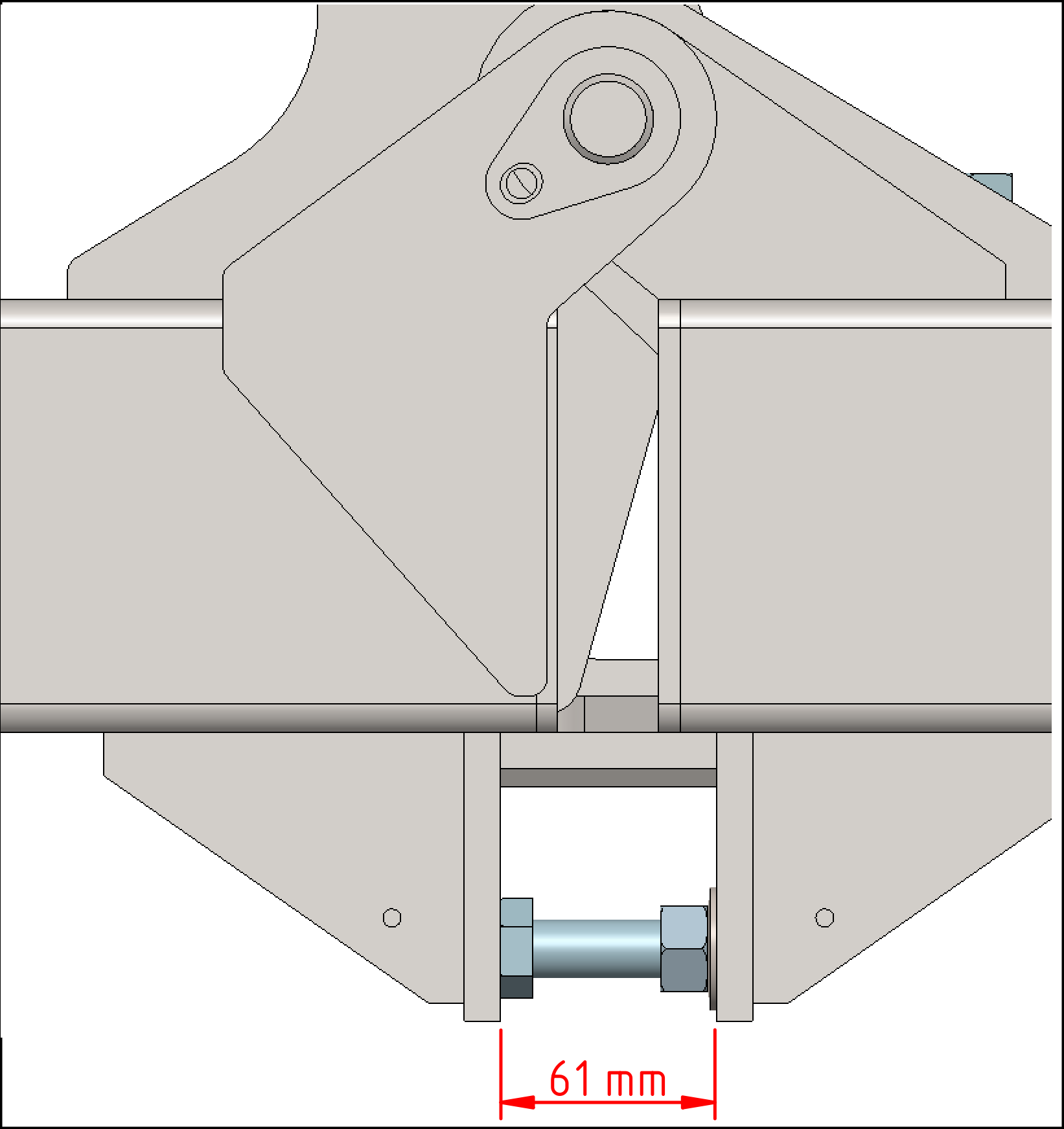
Horizontality of the units
If the units must be horizontal without touching the ground, the stop screws must be adjusted so that they come out 61 mm | 2.4 in. There are 6 screws to adjust.
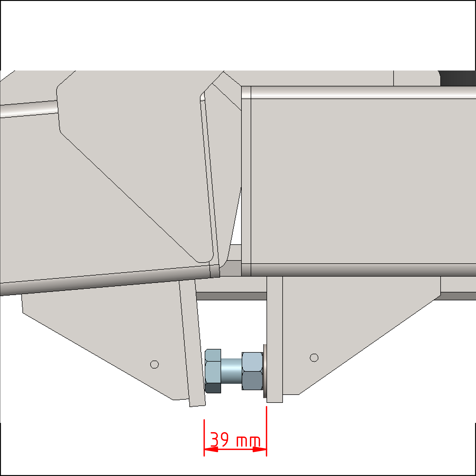
INFORMATION
These screws must be adjusted to their initial position (39 mm | 1.54 in) before the machine can be used normally again.