-
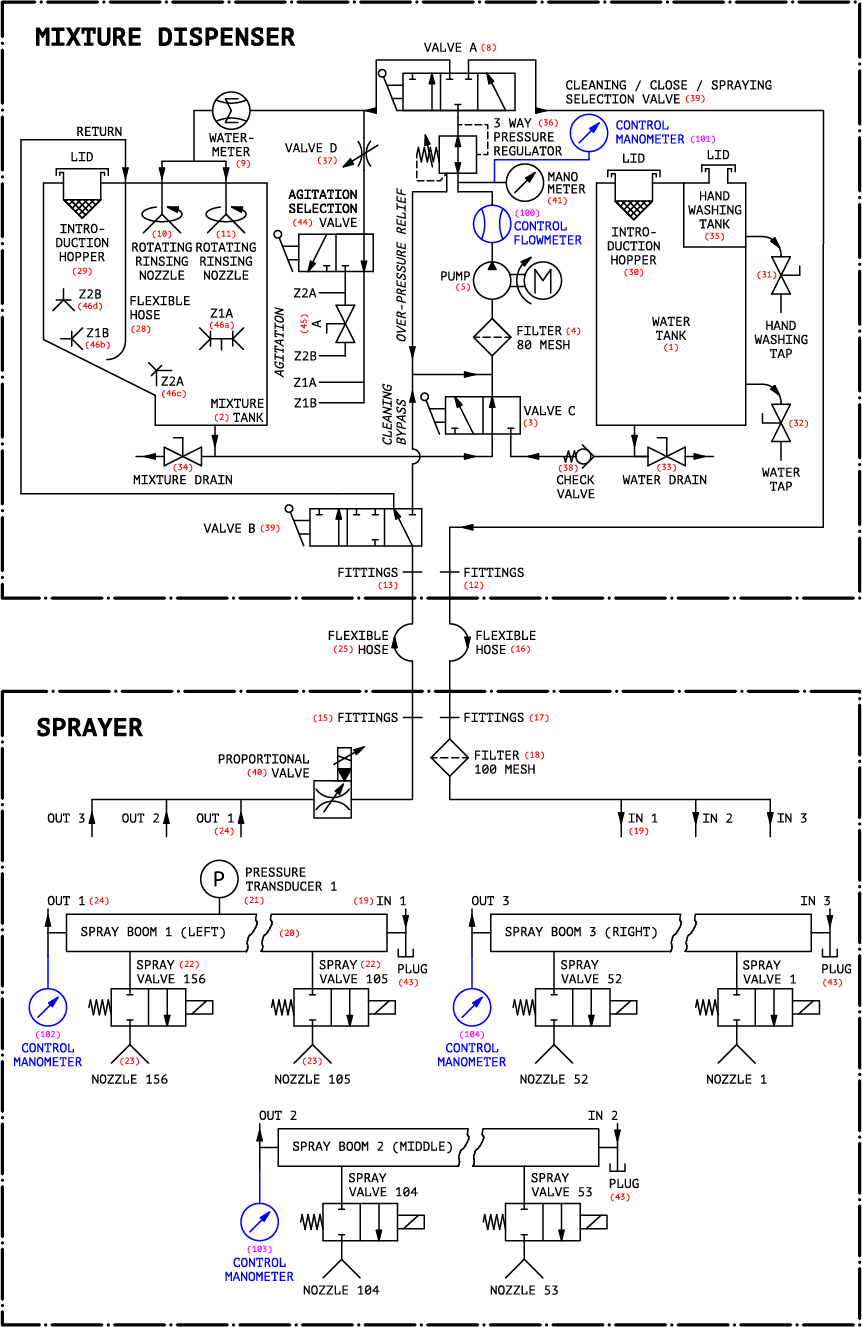
(1) Clear water tank.
-
(2) Mixture tank.
-
(3) Fluid type selection valve (type 3/2): allows selection of clear water or mixture.
-
(4) Suction filter: protects the pump (5) from impurities.
-
(5) Pump: puts in motion the selected fluid (3) with an adjustable flow rate. The pump is hydraulically driven.
-
(8) Valve 2/2: for rinsing and filling the mixture tank (2).
-
(9) Totalizer: this component displays the volume of fluid introduced into the spray tank (2) by the flushing circuit.
-
(10), (11) Rotating rinsing heads: allows the rinsing of most of the walls of the mixture tank (2).
-
(12), (13), (15), (17) Connections: quick connectors.
-
(16), (25) Hoses: allow fluid distribution between the dual tank module and the spraying module.
-
(18) Section filter: protects the nozzles (23).
-
(19) 3-way distributor, incoming: allows the fluid to be distributed among the three spray booms.
-
(20) Spray boom: includes 52 nozzles (23) and associated solenoid valves (22).
-
(21) Pressure sensor: measures the pressure in the middle of the spray boom (20) and returns the value read to the control system.
-
(22) Solenoid valve of nozzles: allow the activation and the deactivation of the nozzles (23) according to the detection of the plants.
-
(23) Spray nozzles: for optimal distribution of the products to be sprayed.
-
(24) 3-way return distributor: This distributor merges the flows from each spray boom (20) into a single return flow.
-
(29), (30) Incorporation filters: these filters prevent the introduction of unwanted particles in the tanks.
-
(31) Hand washing valve: This 2-way valve allows for hand washing.
-
(32) Clear water valve: this 2-way valve allows to draw water from the clear water tank (1) at low flow rate.
-
(33) Drain valve of the clear water tank.
-
(34) Drain valve of the mixture tank.
-
(35) Mini water tank: This tank allows to have clean water available for hand washing.
-
(36) 3-way pressure regulator: this regulator allows to regulate a pressure in the fluid circuit.
-
(37) Agitation valve: this proportional valve is used to select agitation power in the spray tank (2).
-
(38) Non-return valves: these valves prevent contamination of the clear water tank by mixture.
-
(39) Return flow direction valve: it allows to direct the return flow according to the use. The "Cleaning" mode allows the fluidic circuit to be rinsed with clear water without diluting the mixture. The "Close" mode allows to disconnect the pipes 25 and 16 without siphoning the tank. The "Spraying" mode allows normal operation.
-
(40) Proportional valve: this electric valve allows an active regulation of the pressure during spraying.
-
(41) Manometer: this manometer indicates the pressure in the pressure regulator (36), and by extension in the fluid circuit.
-
(43) Boom drain plugs: These plugs, once opened, allow to completely drain the spray booms (20) and thus protect them from frost.
-
(44) Agitation selection valve: this valve allows you to select the agitation zone (Z1 ou Z2).
-
(45) Isolation valve: this valve is used to activate or deactivate the Z2B agitation nozzle.
-
(46) Agitation nozzles Z1A, Z1B, Z2A and Z2B.
-
(100) Connectors for connecting a flow meter to control the flow rate at the pump outlet (5).
-
(101), (102), (103), (104) Control manometers: 1/4″ BSP connectors allow the connection of manometers to control the pressure at different points on the fluidic circuit.